
Projection Welding
Questions and Answers
This is an interesting question. Most people are concerned about the height of the projections varying or not being present. The flatness of the base metal is considered a given. Any variation in the projection or the base metal that creates the same gap can lead to a welding issue. The question is how much gap can be tolerated.
After the force is applied before the current is initiated full projection set down is needed to eliminate all gaps in order to prevent material expulsion and maximize weld strength. Gaps in a ring projection or multiple projection all have the same requirement for flatness. Flatness helps to make complete set down and full contact to ensure the current is evenly conducted through all of the projection areas at the same rate. This will maximize nugget formation as desired either as a ring, single or multiple projections.
A search of the literature found one source that listed allowable tolerances for projection heights.
AWS C1.1 – “Recommended Practices for Resistance Welding”
Table 46 listed a height tolerance up to: +/-1.27 mm (+/-0.005 in) for material over 1.27 mm (0.050 in) thick.
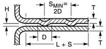
PROJECTION HEIGHT "H"
For thinner material and complete information consult AWS C1.1 – “Recommended Practices for Resistance Welding."
Reference: AWS C1.1 Recommended Practices for Resistance Welding
RWMA - Resistance Welding Manual 4th Edition
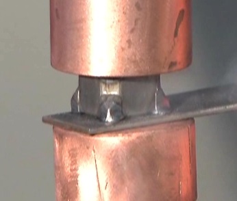
Resistance welding weld nuts is a projection welding process. In projection welding the part has been formed by design or shape to deliver the force and current at predefined generally small points, shapes or circles. In the case of weld nuts the power is delivered through several small points. Each projection will develop a normal weld nugget. This form of resistance welding uses the part to concentrate the heat and force not the electrode.
Due to this unique design feature the size of the electrode is not a factor. The electrode is normally flat and at least the size of the part mating surface. It should be larger than the projection weld pattern area to prevent heat buildup and provide support to the part. The size of the electrode has little influence on the weld since the projection concentrates the current and force not the electrode. Factors besides the part size that might influence the electrode selection could be: the available equipment, available tooling, expected power requirement and anticipated force. The electrode should be larger than the part being welded as shown.
PROJECTION WELD NUT
In ring projections the electrode diameter should be at least twice the diameter of the projection ring. So the answer is yes it could be a 6 and 8 MM electrode mix is they fit the parts properly. Or two 8MM’ s if you want common electrodes to reduce electrode inventory?
In some welds individual electrodes are used on the one side and a common bar electrode is used on the other side. Fencing can be projection welded in this manner.
Reference: AWS Standard C1.1 Recommended Practices for Resistance Welding
RWMA – RWMA Resistance Welding Manual 4h Edition
Resistance welding weld nuts is a projection welding process. In projection welding the part has been formed by design or shape to deliver the force and current at predefined generally small points, shapes or circles. In the case of weld nuts the power is delivered through several small points. Each projection will develop a normal weld nugget. This form of resistance welding uses the part to concentrate the heat and force not the electrode. The traditional weld cycle is squeeze, weld, hold. This is the same as a traditional spot weld. Preheats are not normally used in projection welds.
It is very common operation to weld threaded projection nuts and studs to parts. It is one of the most common fastener systems used in industry. Yes, weld a projection nut to the desired bracket. Spot welding a nut to a steel part could create obstacles due to the large surface area and mass of the nut versus the steel part. Projections on the weld nut eliminate this situation.
Projection nuts are available in many configurations:
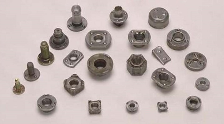
PROJECTION WELD NUTS AND STUDS
Automated feed systems are available for the production of many thousands of parts. Standard machines and processes are available for processing nut and stud components.
References: RWMA – Resistance Welding Manual 4th Edition
AWS – AWS Standard C1.1, Recommended Practices for Resistance Welding
Weld nut set down can be defined as the gap between the weld nut and the stamping. Parallelism of the set down is also a consideration for many applications. At this time there is no accepted industry standard for weld nut or projection weld set down.
The type of part. It’s location in the assembly. The method that force is applied in use. Is it a safety application? Will a coating be applied? These and many other design issues may influence the set down standard being applied to the part. Industry has not developed a common standard.
Projection Nut Weld
Below is a sampling of a few simplified descriptions of set down and parallelism applied by different OEM’s.
OEM-1
…shall be set down so that the gap between the base of the fastener and the mating part is no more than 0.3 mm or 30% of the pre-weld projection height (whichever is less) and is not a criterion for welds to be discrepant…
…side-to-side gap shall not differ by more than 0.2 mm, but is not a criterion for welds to be discrepant…
OEM-2
…the fastener maximum gap is 0.1 mm, with a target value is 0.00 mm…
OEM-3
…discrepant if the gap between the welded parts exceeds 20% of the original projection height…
OEM-4
…parallelism of the welding projections of max. 0.1 mm relative to the contacting surface…
As can be seen from the above snippets of information, no one agrees with any one. The values are either percentages of projection heights or hard values, or both. Some consider anything in excess of the stated values to be cause for a weld discrepancy, while others do not. Some address both Set-Down and Parallelism, while others address only one, or the other. Frankly, this level of inconsistency with regard to a single data point is rare in the welding industry.
The possible reasons for these differences are varied. However, they can be boiled down to a few board categories.
• In-Process vs. Structural: Are the projection welds in question strictly manufacturing welds, or are they needed to carry an actual load? An example of a manufacturing application might be a weld nut that has a subsequent bolt and assembly process that might be critical, but once torque is achieved, the welds on the actual nut could instantly disappear and there would be no loss of functionality. Reparability might suffer, but the final product will be fine.
• Type of Loading: The vast majority (but not all) of PW applications have the load applied to the part in a compressive nature. It does not take much imagination to visualize the various OEMs processing their PW applications in differing manners (think applied loads in tension or shear), each with their own level of acceptability requirements.
• Assembly Issues: In some cases, the design can be so tight that excessive (or even moderate) Set-Down values might result in part fit-up issues. This can be seen in areas where many items are coming together in a confined space. As an example, an automotive B-pillar.
• Issues in Paint: While less common, it is possible for the space between the welded parts to act as a trap. The vast majority of weld nuts are located in areas where this not an issue. However, in those cases where any kind of redeposit can occur, you can bet the chorus requesting a ‘Zero’ Set-Down weld will be loud and persuasive.
Taken as a whole, it is best to keep the set down the value to less than 20% of the projection height. As indicated from above one can run into issues even with this ‘Rule-of-Thumb’ due to varying base metal gauges, coatings, and strengths.
References: RWMA – Resistance Welding Manual 4th Edition
AWS – AWS Standard C1.1 Recommended Practices for Resistance Welding
Technical Input by - DONALD F. MAATZ Jr.
Page 4 of 21
Have a Question?
Do you have a question that is not covered in our knowledgebase? Do you have questions regarding the above article? Click here to ask the professor.