
Controls & Transformers
Questions and Answers
When the operator actuates the foot switch, a signal is sent to the resistance weld control to actuate the weld cycle. On a typical simple weld cycle the control would initiate:
SQUEEZE – the time for force to build up and contain the work piece
WELD – time of current flow/heating and weld nugget generation
HOLD - nugget cooling, containment & forging
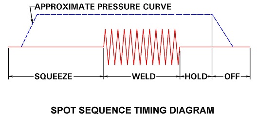
Current does not flow until the squeeze time has been completed. The time from foot initiation to current flow depends upon the length of the squeeze time. The foot pedal has nothing to do with the current initiation.
The welder control initiates the current at the proper predetermined time in the weld sequence. If the squeeze time is short the current initiates quickly. If longer, current initiation is delayed. Squeeze should be adequate to allow force build up to prevent/reduce expulsion.
References: RWMA Resistance Welding Manual 4th Edition
AC systems were the go-to systems for many years for almost all spot welding. They were consistent, reliable, available and lasted forever. DC systems were large and costly. With electronics, MFDC emerged, and DC became economical and transformer size for DC was reduced. It became possible to use more payload on the end of a robot arm and MFDC became the means to increased automation. It was more power with less weight than an AC transformer could deliver. All automation systems are pretty much MFDC today.
The cost for the mfdc weight advantage is a more costly system and probably a shorter total life span. That may operate with 20% less power usage? AC equipment is very reliable for a very long time.
For a complete understanding of MFDC vs AC read the article:
COMPARE MFDC VS AC IN RESISTANCE WELDING?
The ability to control at the millisecond level can improve quality control. This is where real money can be saved by fewer rejects or rework.
In today’s market estimates of new systems are:
Automotive:
MFDC 95%
AC 5%
Commercial Goods:
MFDC 50%
AC 50%
Both MFDC and AC are good reliable systems. MFDC is the choice for automation. In other applications it comes down to what will work best in your plant with your people.
Reference: RWMA – Resistance Welding Manual 4th Edition
AWS – Welding Journal, Q & A July 2019
This question was recently addresed in another article:
HOW MUCH ELECTRICITY WILL MFDC SAVE VS AC?
Do read the article because it varies by machine and set up. There are many savings advantages and differences between AC and MFDC besides electricity to consider. A simple accepted estimate of power savings might be 20%.
Reference: RWMA - Resistance Welding Manual 4th Edition
As discussed in several articles in this blog the electrodes weld face grows during spot welding. Eventually the electrode must be replaced or the face dressed (machined) back to near original face contour. Depending upon the dressing method the weld current may need to be adjusted.
If a stepper program was being used the current would be reset to the start point and the stepper begins again. If a single current level was used with no stepper, at a restart little adjustment would be expected.
How the electrode was dressed will determine the restart. It is preferred that the electrode face is not refaced during dressing or at least lightly touched. This is meant to reduce the time it takes to reach equilibrium at restart upon the face of the electrode.
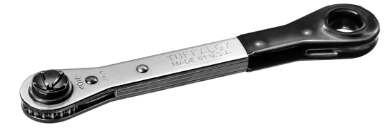
HAND DRESSER DESIGNED TO NOT TOUCH THE FACE
While the oxide layers build up on the weld face and becomes consistent weld face sticking, expulsion and weld nugget variation can be present and erratic. On new electrodes this may take as many as 15-25 welds. On redressed electrodes with untouched faces welding can settle out in fewer welds.
This is referenced in:
How Do I Dress a Resistance Welding Electrode Face
Yes, stepper programs can help increase the life of an electrode. The method used to program controls for stepping vary by control. That needs to be addressed with a control manual or supplier. It cannot be addressed in this blog.
References: RWMA – RWMA Resistance Welding Manual 4th Edition
There are several articles in this blog comparing MFDC vs AC.
COMPARE MFDC VS AC IN RESISTANCE WELDING?
IS DC OR MFDC BETTER THAN AC IN SPOT WELDING?
They explore the advantages and disadvantages of both systems. AC being the long term tried and true with some applications and MFDC being the new comer that has become the main product used on automated lines.
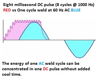
The referenced articles describe the various advantages and disadvantages of both systems. The question raised here is what is the electrical cost advantage. MFDC heats faster than AC since there is no zero cross over. This faster heat up of course will vary by part and final weld schedule. There is no hard value that can be given but the breaker can generally be reduced 20% for MFDC installations vs AC..
Other savings in quality and good part production per shift will generate a much higher value in savings.
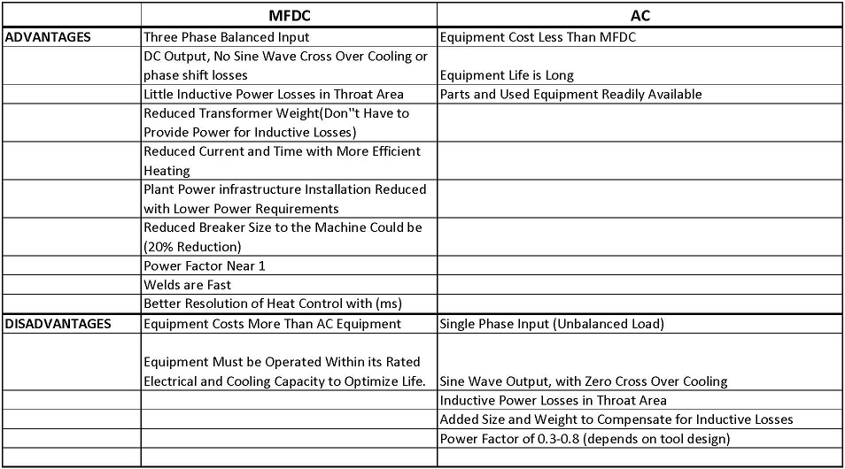
ADVANTAGES & DISADVANTAGES OF MFDC AND AC
Reference: RWMA – Resistance Welding Manual 4th Edition
AWS – Welding Journal, Q & A July 2019
Page 1 of 40
Have a Question?
Do you have a question that is not covered in our knowledgebase? Do you have questions regarding the above article? Click here to ask the professor.