

Spot Welding
Questions and Answers
In this application they are successfully spot welding three thicknesses of 0.019 SS together. When they switch the outer two layers to aluminized coated steel issues arise. They experience need for tip dressing and weld setting changes.
Stainless steel is a relatively resistive material as compared to plain carbon steel and certainly aluminum. When the two outside materials in the assembly are changed to less resistive materials (low carbon aluminized steel), the heat from the part resistance will be lower. More time or current likely will be needed to maintain the same nugget growth.
The electrode for spot welding stainless is either RWMA Class 3 or 2. If the material is changed to aluminized steel RWMA Class 2 would probably be preferred since a higher current may be used to make up for the lower total resistance in the total relative resistance.
As to the coating pickup and added dressing due to aluminum pickup? It will happen. Aluminum melts at a low temperature and is going to be picked up by the electrode face. Welds can be made through it but regular dressing needs to be performed to maintain consistent weld quality.
References:
AWS Standard C1.1 Recommended Practices for Resistance Welding
RWMA - Resistance Welding Manual 4th Edition
As discussed in other articles alignment is very important in resistance welding. It dictates force and current application/distribution and prevents distortion of the workpiece. If not set up properly the part can be distorted and/or the electrode face can have exceedingly high current densities. This can result in distorted parts, expulsion and excessive electrode face wear.
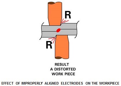
In many shops alignment is done by eyeball?
A better method is a ruler.
Carbon paper has been a good choice for a long time.
Laser lights on the holders is the newest option for alignment.
For additional Information in this blog:
WHAT IS A GOOD WAY TO ALIGN THE TOP AND BOTTOM RESISTANCE WELDING ELECTRODE?
References: RWMA -Resistance Welding Manual 4th Edition
The basic conversion process of AC to DC or MFDC is discussed in an article in this blog:
HOW IS AC CONVERTED TO DC WITH A FREQUENCY OF 600Hz?
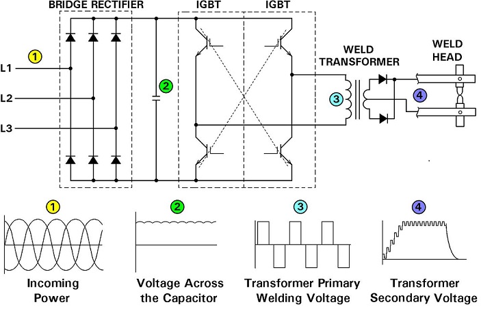
CONVERSION IN CONTROL AND TRANSFORMER of MID FREQUENCY INVERTER
The components and their functions are discussed in the article referred to above. A similar product will be necessary for any high frequency conversion.
The actual design is beyond the scope of this blog.
Reference: RWMA Manual, Fourth Edition
You mentioned that additional cooling apparently has helped a few spots reduce distortion of your thin parts and mesh. Some of your product is seam welded.
Cooling of the electrodes themselves is the most important step. They need lots of water and as cool as possible. An article on this topic is:
HOW COLD SHOULD THE WATER BE FOR RESISTANCE WELDING?
Additionally, the water in the electrode needs to be near the electrode face. In some applications the backup electrode is a large surface or block. This should be a copper conductor and have water passages bored in it for good water cooling.
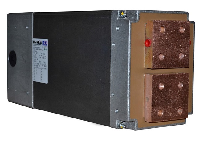
NOTE THE BORED WATER-COOLING HOLES ON THE SIDE
OF THE TRANSFORMER FACE PLATE
This can be one through hole or a series of connected holes depending upon the heat being generated.
In the case of seam welding the water cooling is not near the weld area. An option used frequently for seam welding is flood cooling. Water is sprayed directly on the part at the weld site during the weld. This helps cool both the weld wheel and the part.
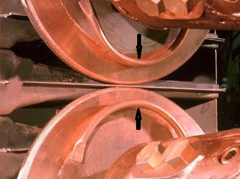
ARROW SHOWS WATER SPRAY COOLING TUBE
To reduce distortion, the part can be held in place by insulated blocks that prevent the distortion as desired until cooling has finished. This is all part of the tool design
Reference: RWMA - Resistance Welding Manual 4th Edition
The final acceptance criteria for quality may be determined by agreement between the manufacturer and the user. Prior to that accepted industrial standards are frequently referenced for possible use in the various applications. One location for these standards is the American Welding Society. AWS publishes technical standards. Many applications with helpful start up data can be found in:
AWS Standard C1.1- Recommended Practices for Resistance Welding
This standard will include tables with data that is applicable to many applications in industry.
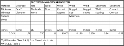
This is an excerpt from a much larger table. There are many tables on many steels and nonferrous materials. Each table offers the same and more information on set up and testing including weld nuggets, shear strength and other weld schedule related data. The processes included are Spot, Projection, Seam , Butt and Flash welding.
Reference: AWS Standard C1.1 Recommended Practices for Resistance Welding
Page 1 of 44
Have a Question?
Do you have a question that is not covered in our knowledgebase? Do you have questions regarding the above article? Click here to ask the professor.