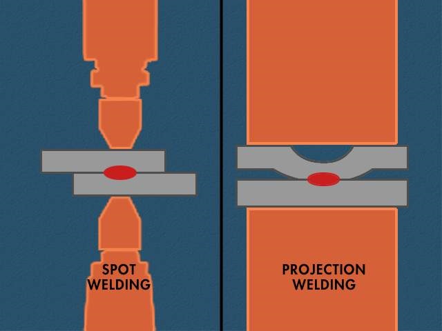
Projection welding is a resistance weld where the design or shape of the part is used to make discreet individual point contacts to concentrate the current during the welding process. In most applications multiple small projections are formed on one surface of the parts to be welded. These projections can be round dimples, elongated ridges, circular, or the extended corners of weld nuts. Two round wires placed together at 90 degrees form a point contact. This would also be a projection weld. When the mating parts are brought together these projections concentrate the current flow and generate the heat in these locations. When the projections get hot they collapse as the weld nugget forms. After cooling the result is several weld nuggets holding the part together. Of course in the case of cross wire welding there is one weld per crossing location but normally many are welded at the same time as in fencing.
The circular ring projection on the bottom of a hydraulic fitting could make a tight hydraulic seal. The cross wire weld could be fencing or rebar in a roadway. The weld nut holds the various parts bolted on your automobile.
The process is the same as a spot weld but in this case the electrode is not used to concentrate the heat. The part projection or arrangement does this. Multiple welds can be made at the same time when multiple projections are present. It is a very efficient process and not as electrode dependent as spot welding. Other factors must be controlled such as alignment, projection consistency, welder follow up and with nut welding, thread protection. Projection welds and processes are designed and developed to fit the various applications.

For additional information see another article in this blog:
What are the Do's and Don'ts for projection welding?
Reference: AWS C1.1 Recommended Practices for Resistance Welding
RWMA - Resistance Welding Manual 4th Edition, Section 1, Chapter 3

