
Controls & Transformers
Questions and Answers
This question is very involved. It depends upon what type of transformer (three phase, single phase, AC, DC). This blog does not get involved with machine design and build subjects. Contact your local machine sources or distributors for information and assistance.
Reference: RWMA Resistance Welding Manual 4th Edition
This question gets into the design of machine components. Design is beyond the scope of this blog. There are several articles describing the components of a transformer and their function in resistance welding. One for MFDC is shown below:
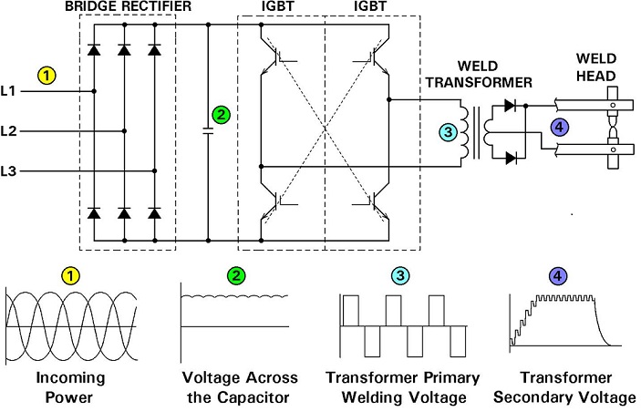
Schematic of Power Conversion In Control and Transformer of Mid Frequency Inverter
Reference: RWMA Resistance Welding Manual 4th Edition
Many resistance welding controls but not all have the ability to operate in more than one language. All controls are different and methods to change the language will vary.
AC CONTROL
Consult you control manual first. Then go to the control manufacturer, a local distributor or equipment dealer for assistance. Information will be available to answer this question.
This blog does not get into the operation of individual machines components.
Pressure is one of the major components of the welding process Pressure, Current & Time (PCT). In most weld schedules pressure is called out as a force value. Pressure is this same value as force but applied to the surface area of the electrode contact face.
Pressure is important because it provides the necessary mechanical force holding the two or more surfaces together during the welding sequence. This insures a good current path and contains the molten metal that may form to prevent expulsion.
The term “Pressure-Controlled Resistance Welding” is not familiar to me.
A question just came in asking what is duty cycle. This has been answered by a previous article reproduced below:
WHAT IS TRANSFORMER % DUTY CYCLE?
Duty cycle is a measurement of the % of the time that the transformer is conducting current during one minute. This value is used to insure that the electrical components are not operating above their thermal capability. Resistance welding transformers are rated at a 50% duty cycle. Each application may operate at different duty cycle up to and including 100% continuous.
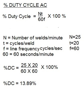
THE FORMULA TO CALCULATE DUTY CYCLE FOR AC is:
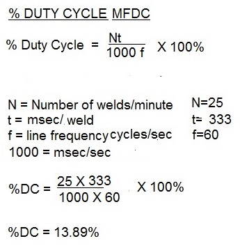
THE FORMULA TO CALCULATE DUTY CYCLE FOR MFDC is:
Other articles in this blog on this subject are:
HOW DO YOU CALCULATE DUTY CYCLE?
WHY IS RESISTANCE WELDING EQUIPMENT DUTY CYCLE RATED AT 50%?
HOW MUCH POWER IS USED RESISTANCE WELDING ON A 150KVA WEKDER?
Reference: RWMA Resistance Welding Manual 4th Edition, Chapter 19
Page 9 of 40
Have a Question?
Do you have a question that is not covered in our knowledgebase? Do you have questions regarding the above article? Click here to ask the professor.