
Controls & Transformers
Questions and Answers
This question is in reference to a previous article:
THE MFDC WAVE FORM DIAGRAM IS NOT CLEAR
The answer is in the paragraph describing point 4. The primary receives an AC input. The transformer contains diodes which convert the AC input to a DC output.
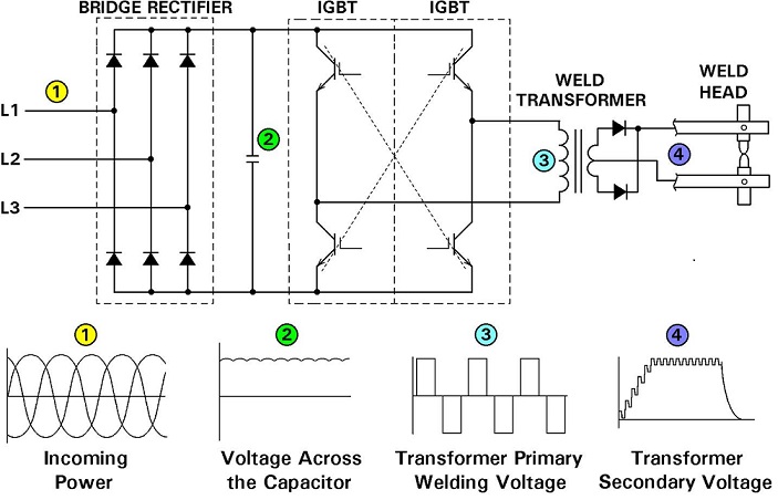
Conversion In Control and Transformer of Mid Frequency Inverter
Reference: RWMA – Resistance Welding Manual 4th Edition
As described in another article:
Constant current is a very useful feature of today’s controls. If this feature is present and you ask for 10,000 amps. The control will deliver that amperage each weld. It won’t matter if you are near the edge of the part or half way across the part. The resistance caused by the impedance is corrected by the constant current. Every weld will receive the same desired current. If you are projection welding one part in the same position each time impedance is not an issue. Knowing that you always get the proper current is a very good feature under most situations.
Another plant variation is line voltage. See the article:
During the day as equipment comes on and off line it can cause the plant supply line voltage to vary. This will create a problem for the control to deliver the proper current output. A constant voltage control corrects for this and will maintain the desired current output. Without this feature the weld current will vary and the projection welds may vary.
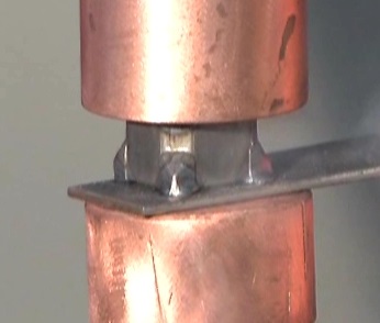
PROJECTION NUT WELD
Refeerence: RWMA Resistance welding Manual 4th Edition
REFERENCES: RWMA - Resistance Welding Manusl 4th Edition
Current monitors usually allow one to set high and low limits around the desired set current. These can be used as an alert that the process is changing and action might be necessary to maintain good weld quality.
Selection of the initial desired set point is determined by the desired quality and the general philosophy of the manufacturing facility. Some facilities prefer to operate near expulsion and others prefer to run midrange in the weld window.
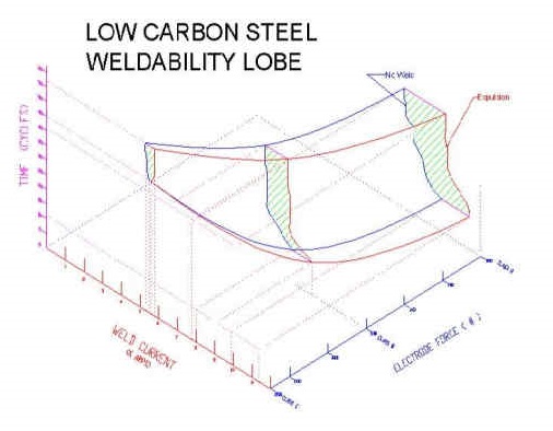
Any point inside the weld window/lobe should produce a good weld. If one chooses to operate on an extreme near expulsion there is little room for error. The alarm would be set very tight? If the current raises on the top side expulsion and overheated burned product could be expected.
Conversely if one operates on the low end. One is risking producing small or a “NO WELD” situation. One never wants to be at the low end and produce small or no welds. Current must exceed this.
The answer is the choice of the operating current setting and any monitor setting alerts around this setting are determined by the individual plant their individual need to meet the manufacturing requirements.
This is beyond the scope of this blog.
Another related article on this subject is:
WHEN SHOULD A WELD MONITOR BE SET UP TO SAMPLE DATA DURING RESISTANCE WELDING?
Reference: RWMA – Resistance Welding Manual 4th Edition
This question was generated from another article in this blog:
HOW DO YOU MEASURE THE INSULATION VALUE OF A RESISTANCE WELDING TRANSFORMER?
?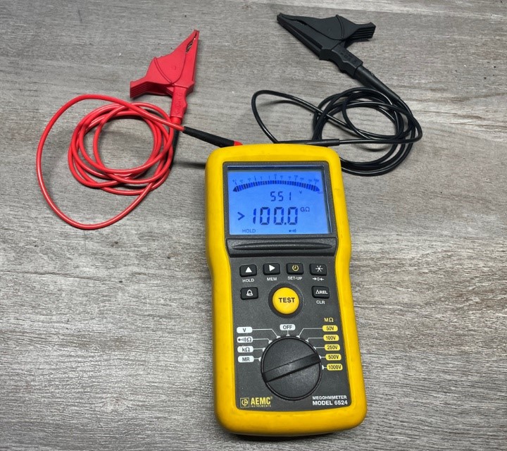
MEGGAR TESTER
The original article describes how to measure the insulation condition of a transformer. This is very important since the insulation is very thin and its failure makes the machine inoperable.
The question is how do you test without causing the damage. The answer was in the original article in the last sentence.
This type of testing should be performed by personnel trained to test transformers. Transformer manufactures can perform this test.
Reference: RWMA Resistance Welding Manual 4th Edition
After reading the article “WHAT IS MFDC WELDING” a reader asked for more detail on how the transformer performs in this process. This blog does not go into specific equipment detail but there is another article which has more detail of the functions of the MFDC control and transformer:
IS THERE A DIFFERENCE BETWEEN MFDC AND AC RESISTANCE WELDING TRANSFORMERS?
This articles answers the question of how the MFDC transformer functions and how it handles the voltage and current.
Schematic of Power Conersionin Control and Transformer of Mid Frequency Inverter
Reference: Entron Controls, LLC
Page 3 of 41
Have a Question?
Do you have a question that is not covered in our knowledgebase? Do you have questions regarding the above article? Click here to ask the professor.