Flash welding uses the work piece as the electrode. A clamp is used to hold the parts and apply force. The entire cross section of the work piece is welded. It is in the timing and the application of force and current that is critical.

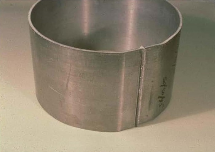
FLASH WELDED WHEEL RIM
Current initiates with the intent of creating an arc between the two workpieces. This generates large amounts of heat on the entire work surface. Large amounts of flash are generated. This flashing action cleans and heats both part mating faces. Then force is applied as the arc current is being terminated. The hot parts are upset and joined together. Power is turned off. Part cools and force is removed. This flash weld joint is very strong.
The upset distance and weld speed is not something that can be calculated. Trial and error tests are the best method to develop the proper settings for the machine and part combination.
The RWMA “Resistance Welding Manual 4th Edition” Section 5 has a considerable amount of information on upset speeds and distances and the variables that are present. For example, RWMA suggests a common upset distance is ½ the part thickness. However, this will vary by alloy up to 1-1.25 times the thickness for high temperature alloys. Aluminum is 50% greater than steel.
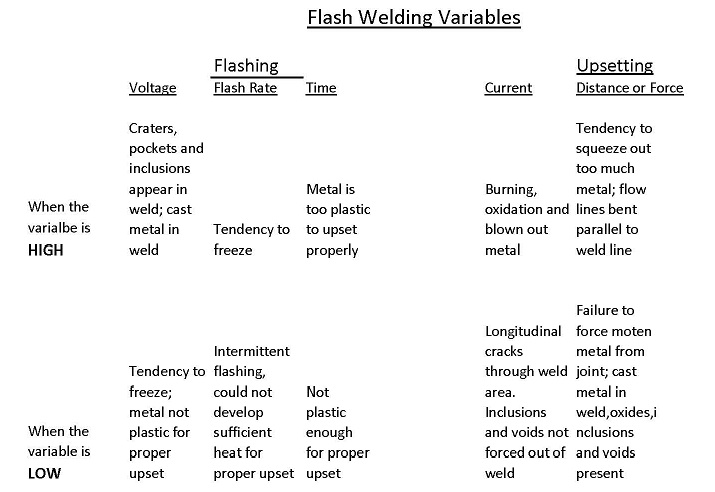
Below is a chart which lists the variables for flash and butt welding and how they can affect the final product.

Refer to the information in the RWMA manual and then perform some trial and error testing to develop the proper settings.
Other blog articles: Can flash welding variables affect the weld?
References: RWMA – Resistance Welding Manual 4th Edition

