In recent years MFDC has become the system of choice for new resistance welding machinery in North America. AC is widely used but for new equipment the preference is MFDC. Automotive and robotic lines use MFDC to take advantage of the weight savings not to mention power reductions and in house primary feed reductions, power factor improvements and others. MFDC does cost more and it is not forgiving if pushed beyond its rated limit.
Its electrical features are excellent in that it heats quickly and does not produce the sine way stitching with the zero cross over cooling. Since it is DC it has virtually no inductance loss when magnetic material enters the throat.
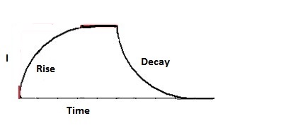
The electrical plot looks as shown below:

PLOT OF MFDC CURRENT
Depending upon the equipment the initial period from initiation of the current till the full current flow is reached takes 3-8 milliseconds (ms) in MFDC. This initial period is called “Rise Time”. When the power is turned off the same curve occurs and is called “Decay Time”.
For additional information about rise time and decay time see the article in this forum:
WHY IS THERE AN INITIAL UPSLOPE IN THE INITIAL CURRENT OF AN MFDC RESISTANCE WELDER?
Reference: RWMA – Resistance Welding Manual 4th Edition
AWS – Welding Journal, Q & A, July 2019

