
If one were to design a weld, the control must provide functions such as squeeze, weld, hold and off. It does this by communicating with the cylinder or servo valve, the SCR or IGBT and or the NC device running the weld cell.
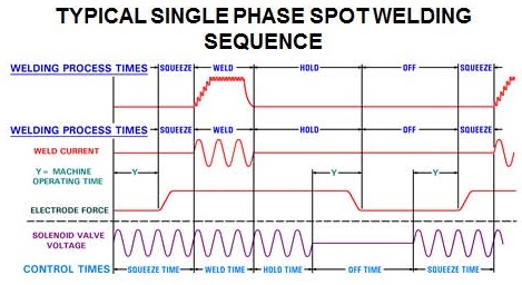
The first line represents an inverter weld. The second an AC weld. The third and fourth lines show the force and solenoid valve functions tied to the force during these functions. It indicates some delay in solenoid action and force application.