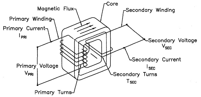
Resistance welding transformers can have very high demand for a very short period of time. Installation of correctly sized primary conductors is imperative for the machine to run properly. The proper procedure to size these conductors for AC equipment is:

When the duty cycle of the machine is known
1. Calculate the duty cycle
2. Determine the weld current
3. Divide the weld current by the turns ratio of the weld transformer. This is the Primary Demand Current.
4. Multiply the Primary Demand Current by the square root of the duty cycle. This is the Primary Effective Continuous Thermal Current (ECTC).
5. Refer to the Ampacity Chart of the cable type to be used. Select the size based on the Primary Effective Continuous Thermal Current (ECTC).
If the Duty Cycle or Weld Current is not known or this is a general purpose machine:
1. Divide the transformer nameplate KVA by the primary voltage.
2. Multiply that result by the square root of 0.5 (RWMA transformers normally are rated at 50% Duty Cycle)
3. The result is the Primary Effective Continuous Thermal Current (ECTC).
4. Refer to the Ampacity Chart of the cable type to be used. Select the size based on the Primary Effective Continuous Thermal Current (ECTC).
Ampacity charts are based on the National Electric Code (NEC). There may be other state, local or company standards that must be followed.
Reference: National Electric Code
RWMA Manual Chapter -21.7
Roman Manufacturing Inc.

