
Spot Welding
Questions and Answers
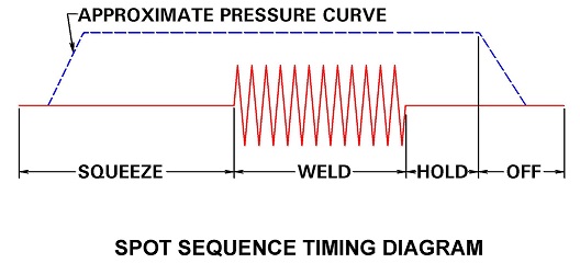
Squeeze time is the first function of the weld sequence during which the electrodes close on the part and build up full force before the control initiates the weld sequence. Squeeze time insures that the part is controlled and under the full force of the electrodes before amperage is applied. This contains the current flow to an area to heat, prevents flash and produces a good weld nugget.
In push pull resistance welding two transformers are arranged opposite each other such that the opposing electrodes are opposite polarity and from the opposing transformer, as shown below. This arrangement is advantageous for making many spots in automated systems. All cables can either be above or below.
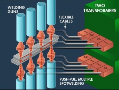
The question is how many SCR’s are required and how are they sized? In the above one SCR would control both transformers, fired at the same time. Therefor the sizing of the SCR would be based upon the total current draw and sizing of the two transformers making the four welds.
To size a transformer see article: “HOW TO SIZE A TRANSFORMER”
Reference: RWMA Manual- Fourth Edition
All spot welding electrodes will wear. It eventually appears in the form of mushrooming. To counteract this and keep the process going there are two options. One choice is to use a current stepper to match the face growth with small current increases every so many welds. The other choice is to dress the electrode face back to its original size before its growth has caused degradation in the weld quality. Without current increases the weld fails because the electrode surface area is too large for the current being used. The current density has dropped. The figure demonstrates this current density change.
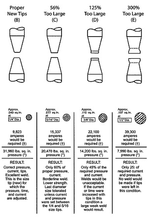
ELECTRODE WEAR VS POWER
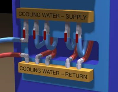
All suspended gun systems consist of potentially four components that may require water cooling. They are the control, the transformer, the secondary cables and the electrodes with their copper holders. The traditional suspended gun systems would have all of these components. Newer systems may use transguns, which would eliminate the secondary kickless cables.
Depending upon your system, an input and output water manifold would be assembled similar to the one shown below. The output and input water lines would be routed to the components that require water cooling. The plant water supply would be connected to the supply side of the manifold. This could be city water, plant water tower system or a chiller. The return would connect to a sewer drain, water tower return or chiller return.
WATER MANIFOLD
A DC transformer in this case refers to the traditional 50/60 Hz three phase transformer used for many years for high power requirement. These low frequency transformers are high power machines capable of long duty cycles. These tend to be large transformers due to their power ratings and applications.
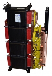
DC LOW FREQUENCY TRANSFORMER
Page 23 of 47
Have a Question?
Do you have a question that is not covered in our knowledgebase? Do you have questions regarding the above article? Click here to ask the professor.